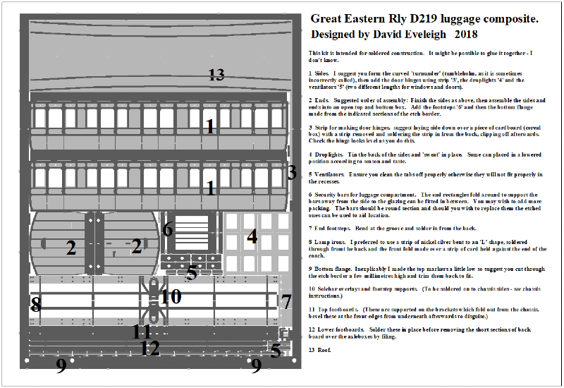
I have chosen to illustrate the building of the D219 Luggage Composite coach. It has all of the elements of the other coaches except the duckets which are fitted to the brake coaches – I have included a section on those.
What is included in the kit
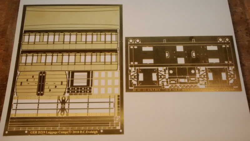
The main etch includes the body, and the solebar overlays and footboard supports.
These instructions can be downloaded from the website.
The other etch contains the main parts of the chassis. Like the four wheeled coach chassis, I needed to accommodate two different lengths: 32’0” with 10’0” + 10’0” wheelbases or 34’6” with 11’3” + 11’3” wheelbases. This was achieved in the same way as with the four wheeled chassis and rather than explain that again I would refer you to my build sequence for that item here. This coach uses the chassis in its shorter configuration.
Chassis first …
The main build is exactly as the four wheeled chassis. Only a couple of differences need to be covered:
Restraining the rocking ‘W’ iron
Unfortunately I had a momentary lapse and provided hippopotomuses rather than elephants. The little fold up units which hold the rocking ‘W’ iron in between its guides do not prvide lateral restraint, meaning the ‘W’ iron unit can slide sideways. This is easily correctable in a number of ways: I suggest a couple of strips of 0.75mm thick plastikard either side, or drill for a central locating pin which is soldered either to the ‘W’ iron unit and pokes through the floor of the chassis or vice versa. Apologies.
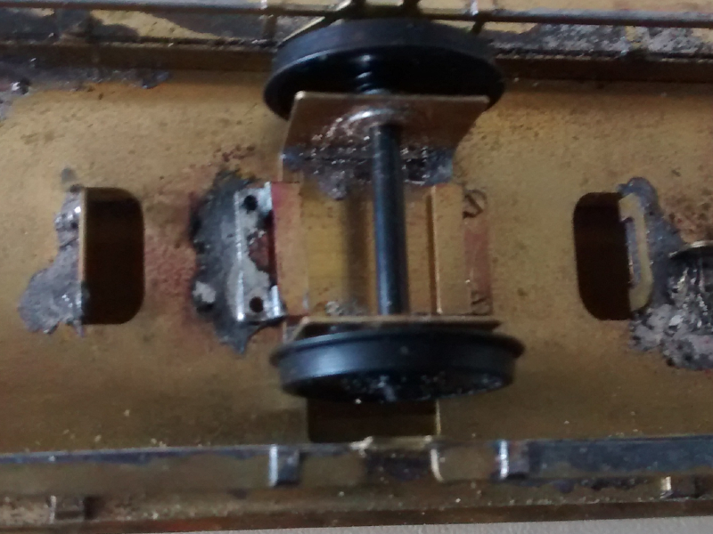
Centre Axle Unit
This folds into a ‘U’ shape and needs a pair of 2mm bearings (available from Eileen’s Emporium among other places). Reinforce the folds with a fillet of solder. It is an internal bearing unit so you will need to remove one wheel from the axle and press it on carefully again to the correct back to back measurement once the axle is fitted through the unit.
The unit is held in place by two little brackets which fold to a lazy ‘z’ (two right angle bends). The side which mounts on the floor has two holes in it with the idea that it can be located with wires pushed through whilst soldering. In fact I opened up the holes and mounted one of the brackets with nuts and bolts so that the centre unit is removeable.
The whole thing is kept very loose and you may find that in operation running on your model railway adjustments need to be made. The fold down ‘C’ shaped features in the chassis floor were put there with the idea that a stiff wire could be soldered longitudinally to the centre unit and these would restrain the unit from any tendency to rotate about an axis parallel to the axle as the vehicle moves one way and then the other. It is up to the builder whether he or she feels this is necessary.
Body
This follows pretty much the methods described in the build sequence for the four wheeled coach bodies and you may wish to refer to that for added detail.
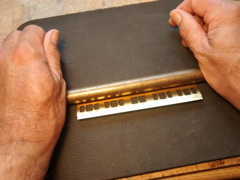
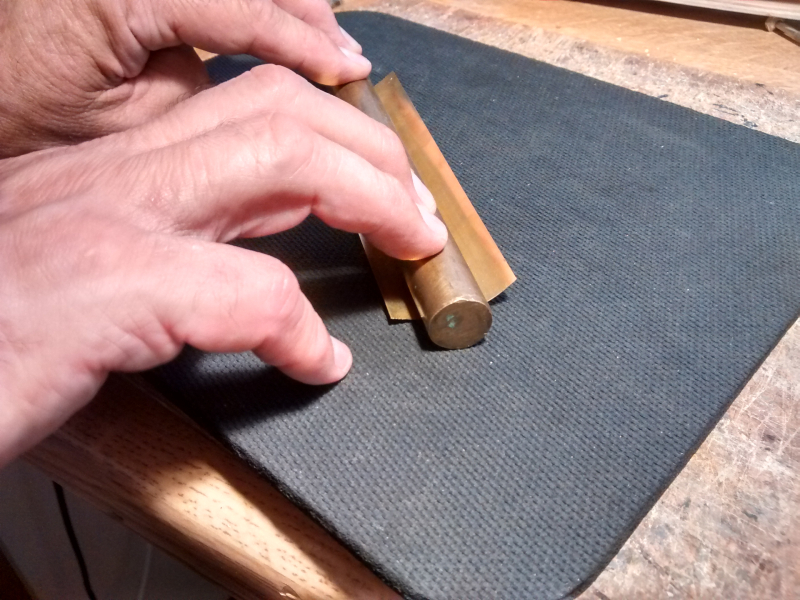
Turnunder
Start by rolling the ‘turnunder’ (sometimes incorrectly referred to as a ‘tumblehome’) using a piece of bar on a mouse mat.
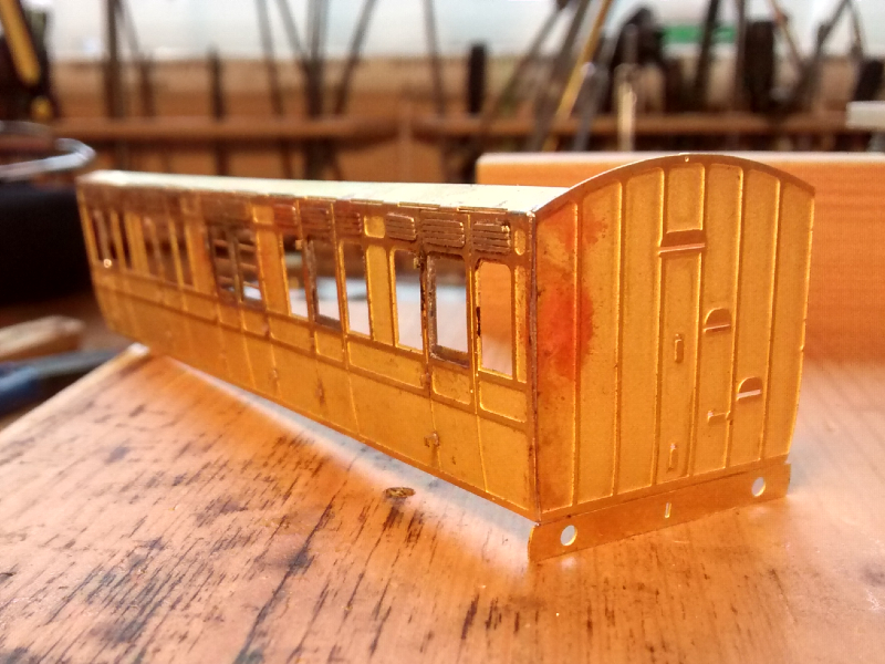
Add the door hinges
Hold the side face down over a piece of cereal packet card (or similar) with a slot to give the required relief. Check that the hinges are all horizontal (including the one which emerges from the waisted portion of the side near the bottom) before snipping off behind and filing flat.
Add drop lights.
Tin the back of the side and then trap the drop light under the side in the correct position before ‘sweating’ in place.
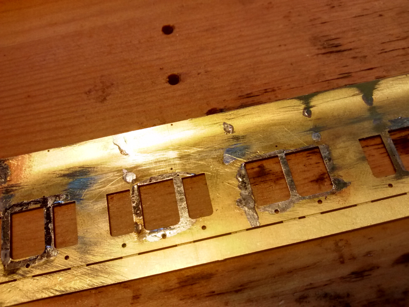
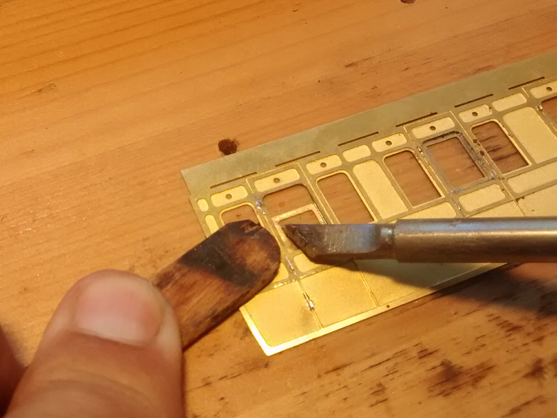
Ventilators
The ventilators (two different lengths for over the side windows and over the doors) need the tabs cleaning off carefully in order for them to sit down properly in their recesses. You want to make sure they are well positioned – it looks really bad if they are higgledy piggledy. Positioning the ventilators is easy, using two of the smallest jewellers screwdrivers before soldering in position. You need to keep the solder to a minimum to avoid filling up the grooves – easiest to tin the backs and press them down with a dry iron.
The little holes in the panels under where the ventilators go fulfill three purposes: they show which panels need ventilators (There are more of them on the First Class coach.); they reduce the chance of the ventilator being jogged out of position by escaping steam when the soldering iron is applied; they allow more solder to be added from the rear once the ventilators are fixed from the front and you are happy with the position. I have found that is is very easy for ventilators not to be fixed securely and for them to fall out at a later stage, so this is an aspect worth attending to carefully.
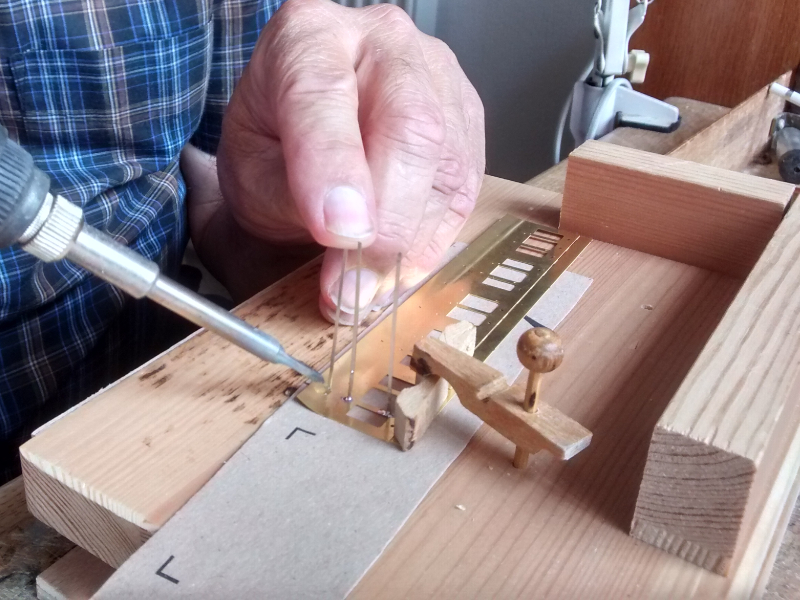
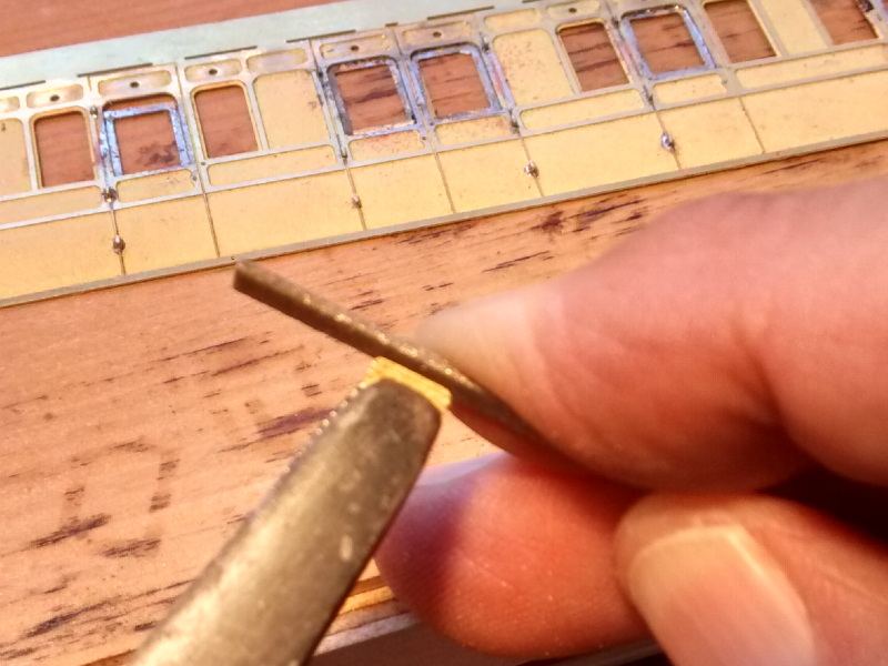
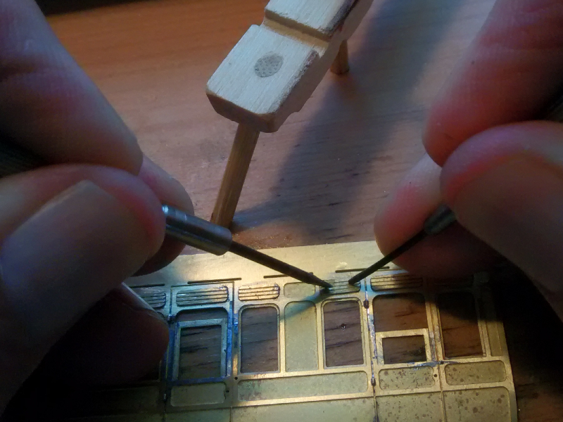
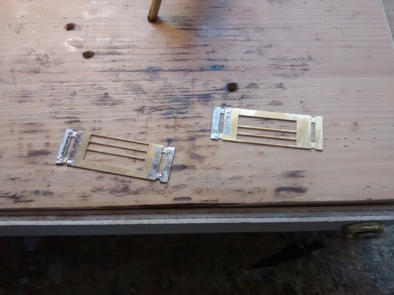
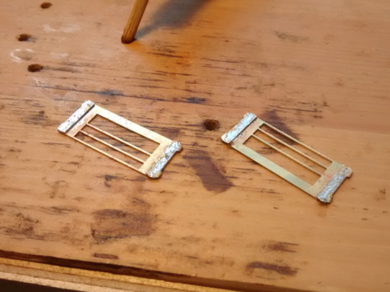
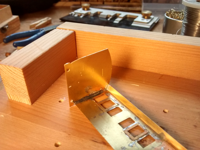
Security bars in Luggage Compartment
The side rectangles fold over and provide a gap between the bars and the side of the coach into which the glazing may be inserted. Depending on the glazing material you are using, you may wish to add another layer using scrap etch to increase the gap. The bars should be round section and you may choose to replace the etched bars with wire, using the position of the etched bars where you have chopped them off near the end as a guide.
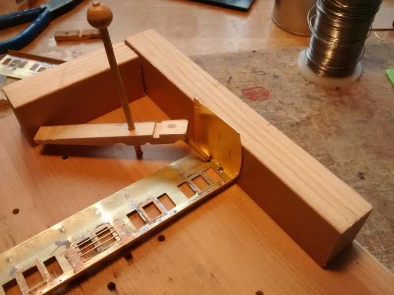
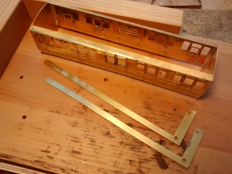
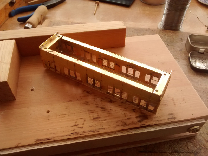
Assembly of the coach body
It is wise to assemble the body at this stage before the end footsteps are added. I am supporting the sides and ends against the fence on the Orion Jig. Go gradually. The ends need to have their turnunders formed and then the headstocks (bufferbeams) bent back vertical. Tack in one place – take the side and end out and check the alignment top and bottom – tack in a second place and when happy run the seam along.
The flange along the top provides rigidity and helps provide a good surface for fixing the roof to.
A well formed corner – don’t worry about the discolouration. That can be cleaned off and won’t show under the paint.
Part of the etch border forms a flange around the bottom of the body of the coach. This provides strength and rigidity, and a fixing for the chassis.
Somehow I put the indicating markers slightly too far down on the side and so there is a little gap. This can be avoided in subsequent builds, and now you have been made aware you can avoid the same mistake.
I filed chamfers at the corners to allow the flange to sit snuggly against the sides and the ends even if there was a meniscus of solder where the actual corner is.
The holes in the corners of the flange match with holes in the chassis. Small nuts can be soldered over the holes in the body and then the chassis can be bolted to it. I suggest 8BA would be about the correct size. Use a steel bolt temporarily to hold the nut in place, putting Vaseline on the thread, and this will avoid the bolt getting soldered to the nut.
Adding footsteps and lamp irons
The coach body can be held quite easily, cantilevered out over the edge of a piece of packing, whilst the footsteps are soldered in from the back and the lamp irons added. I have provided little strips of etch with grooves to form lamp irons, but prefer to use plain strips of nickel silver (etch waste from my 2mm scale kits) bent to an ‘L’ shape – soldered in from behind – piece of card pushed against the top surface of the strip as it emerges and bend the strip upwards, trimming to length afterwards.
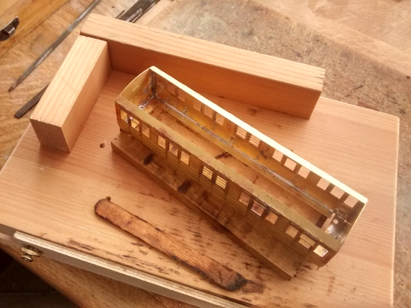
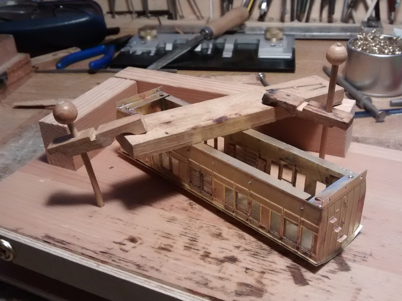
Roof
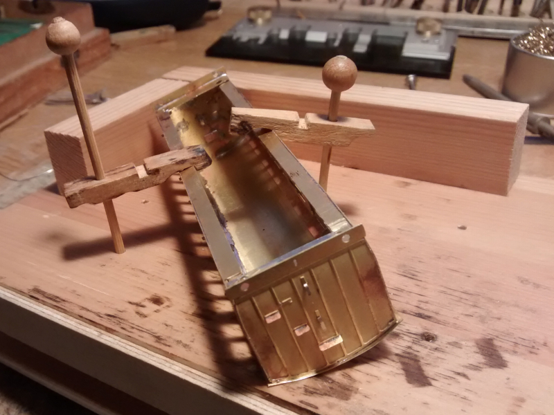
Curve the roof over a mousemat using a piece of bar.
The coach body held level with the roof carefully centered underneath. A single tack of solder is placed at each end.
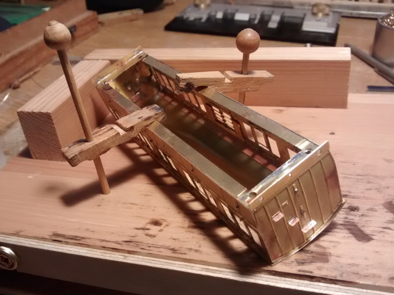
The coach body is tilted over using the half cloths peg clamps so the seam can be run along one side. I would think of a different way to do this – probably with a long strip of wood between the clamp and the base of the coach side – because it is easy to solder the roof on in such a way that the coach body is twisted.
The coach is reversed, with the other side held down and the fixing of the roof completed.
The final stage on the body is to add the headstock thickeners on the insides of the headstocks at the ends – which I forgot to photograph. (It is covered on the Four wheeled coach body build sequence.)