This kit is intended for soldered construction. It is probably possible for it to be glued together, but soldering is quicker and almost certainly stronger. This sequence shows how I soldered the kit together.
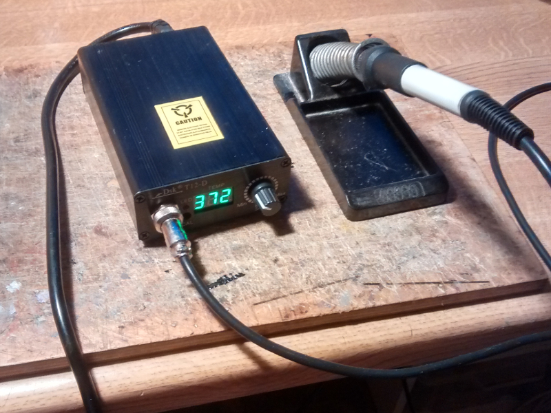
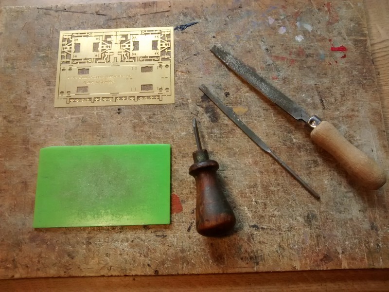
For strength and rigidity, I designed the kit and had it etched in 0.4mm thick brass. This means that a fairly powerful soldering iron is needed. I used a very nice unit I bought recently from Ebay which was described as a ‘T12 LED digital Soldering Iron Station Temperature Controller + T12 Handle.’ At time of writing there seem to be several options available and they cost around £30 – £40. A nice feature is the wide variety of bits available. I used the largest of the chisel shaped bits to achieve maximum heat transfer.
I use 60:40 Lead tin solder (not Lead free – I find that unuseable as the surface tension is too high, causing it not to ‘wet’ the surface easily). I use 12% phosphoric acid flux which is obtainable from London Road Models and other model railway suppliers. Recently I have been trying Telux flux as someone said it might be kinder to soldering iron bits
The flux has three main effects. It stops the metal from oxidising as it is heated; reduces to surface tension of the solder allowing it to flow into the joints; makes a nice sizzling noise telling you when you have achieved an effective heat transfer. (Avoid it spraying in your eyes as it boils off, however, and avoid breathing the fumes from the rosin flux core of the solder.)
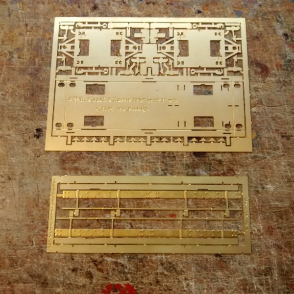
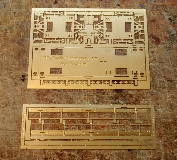
What you get in the kit:
Base unit + short solebars and footboards for Brake Third class coach.
Base unit + long solebars and footboards for First or Third class coach.
This parts list and instruction set can be downloaded from the website.
The coach kits this chassis is designed for came in two different lengths and with two different wheelbases. To make things economical and to avoid waste I designed the main part of the chassis to be adjustable, but you do need to specify which length you are building when you buy the chassis, to ensure you get the correct solebar overlays.
It would be possible to use this kit for other coaches and it would be quite easy to adjust the wheelbase and length to suit a variety of coaches.
Cutting out the parts
I use a small chisel and cut the tabs as close to the part as possible, cutting onto a scrap of acrylic (perspex.) The thicker brass used for the chassis kit means cusping along the edges is more noticeable and I tidy those up with a file as shown.
Base unit.
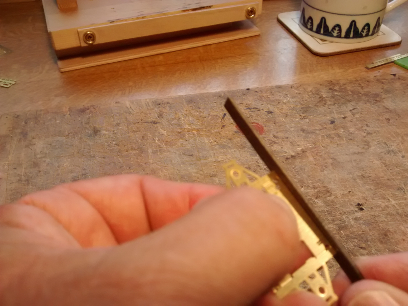
If you are building the shorter version of the chassis you should remove the strips at the ends before folding the sides up. I did this by bending and snapping and then cleaned up the edges with a file.
This sequence shows me building a long version chassis, so I left the ends intact.
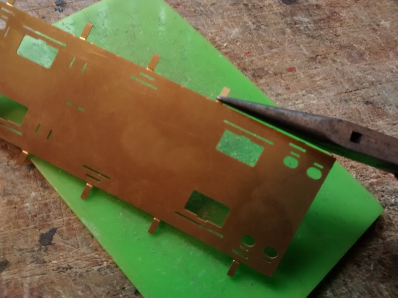
I used a ‘Hold and Fold device to bend the long edges, but it could be done with long bits of bar held in a vice. When I designed the etch I pierced through the folding grooves in the areas where there were cut-outs to avoid distortion. You may wish the reinforce the long bend line on the inside with a solder seam.
Different upper footboard arrangements.
The long chassis version has the upper footboards mounted half way up the solebars using the three slots. These tabs are for the short version where the upper footboards are mounted at the bottom of the solebars. I am building the long chassis here so am removing the tabs by bending and snapping; I will clean up the edges in a minute with a file.
Adding the solebar overlays
I am assembling this kit on one of my own designed ‘Orion’ Jigs. (‘named after the arrangement of holes I put inthe base for mounting the half peg clamps.) These greatly facilitate etch assembly and general modelling. They are easy to make, but I have them available here if you would like to obtain one directly from me.
First clean and tin the backs of the solebar overlays and the edge of the base unit. I am holding the chassis on edge here in the chassis clamp part of my ‘Orion Jig’. Clean up the surfaces with a fibre-glass pencil, steel wool or abrasive paper. This allows the flux to catch in the scratches and ‘wet’ the surfaces more uniformly, giving a smoother surface to the solder. You cannot see it in this view, but I tilted the jig up at the back and the ran the iron down from top to bottom, adding more solder as necessary, as I went. Because the board was tilted the wet pool of solder followed the iron. This is similar to the way watercolourists lay an even wash of colour, tilting the board to get the bead of wet paint to keep to the bottom edge.
The solebar overlay is now being added and the upper footboard soldered in position using the three slots through the solbar overlays and the solebars. These can be used to help locate the solebar overlay, adding the two parts in one ‘hit’.
I am using one of the half peg clamp pieces and a lolly stick for holding the footboard in place to protect my pinkies. (Brass conducts heat very very well.) Check as you are going along to make sure the footboard is going to end up horizontal and adjust accordingly.
The lower footboard is held in place using aluminium hair grips (from Eileen’s Emporium) which I have cut down to enable them to grip more firmly. (My hair is very short anyway, where it still exists!)
The long backing strip to which the footboard is soldered needs to be gapped where the axleboxes are – you can see that the footboard is narrower in this region. I do the gapping with a file after the footboard is soldered in place and this helps keep the backing strip straight.
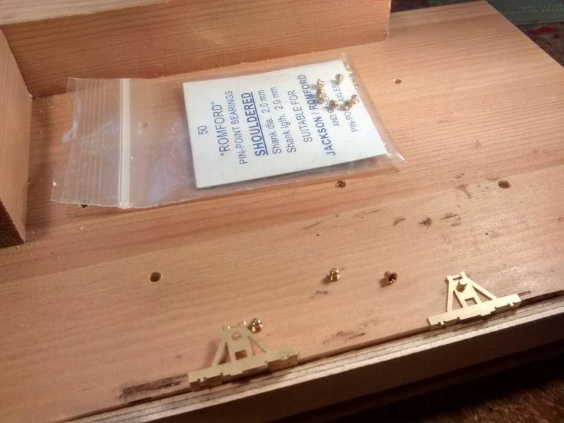
‘W’ irons or Axleguards
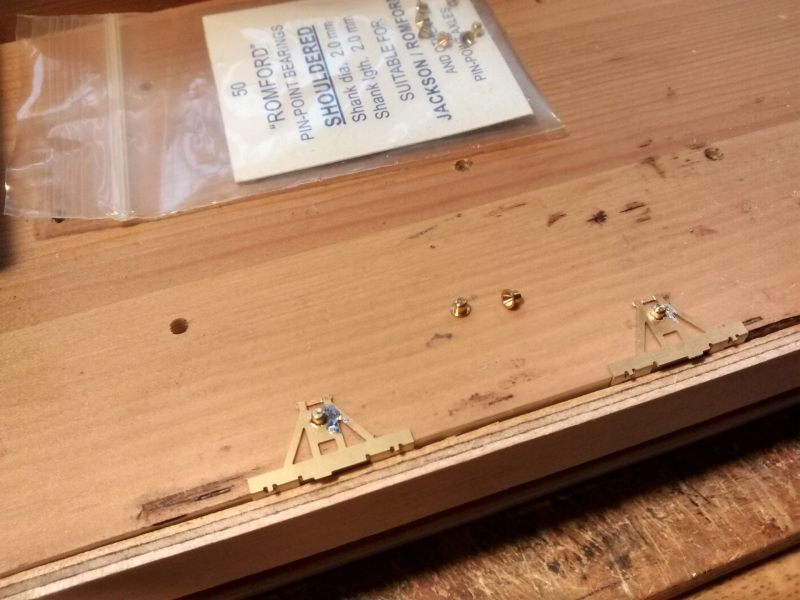
These are now folded up and held in the chassis assembly clamp for soldering the bearings in. The bearings can be filed down at this stage nearly to the level of the ‘W’ iron to allow clearance for the axleboxes.
The folds should be reinforced with solder fillets once you are happy that they are bent to a right angle. The unreinforced ‘W’ iron in the foreground gives a good view of the brake locating slots – inner ones for 00 and outer ones for EM/P4. (The eagle eyed will have noticed that the chassis in the background of this photo is in fact a six wheeled one. Most of the constructional details are the same between the chassis.)
Fixing the ‘W’ irons
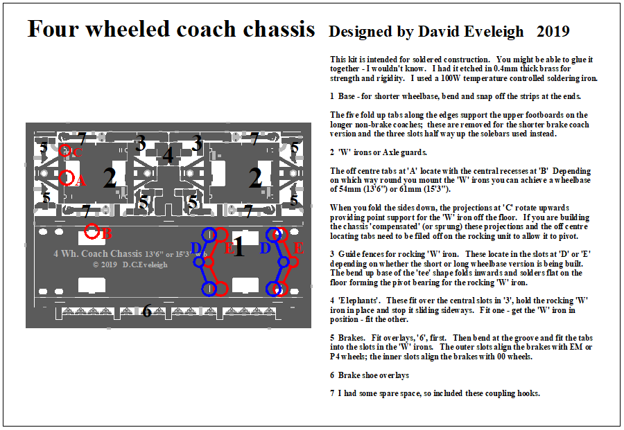
The chassis can be built rigid or compensated (with one ‘W’ iron unit arranged to rock so that all the wheels remain on the track even when the track is a little uneven). The fixed ‘W’ iron unit is located using the tabs which are located asymmetrically near the middle. These slot into the recesses (which are arranged symmetrically) next to the holes for the tops of the wheels in the base unit. Depending on which way round you place the ‘W’ iron the wheelbase (distance between the axles) comes out at 54mm (a scale 13’6”) or 61mm (15’3”). (Cunning, eh?)
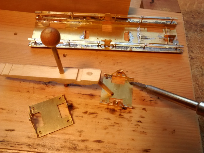
The fixed unit rests off the base on the four small projections near the corners. I found it difficult to get the iron in to make these joints so tinned the base and the ends of the projections and just applied heat from underneath. I reinforced the folds in the ‘W’ iron unit with solder seams at the same time.
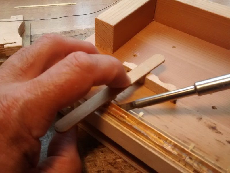
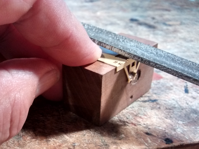
The rocking unit needs to have the corner projections and the locating tabs filed down to give a flat base.
Filing the projections to make the base of the rocking ‘W’ iron flat. (I should really clean my files.)
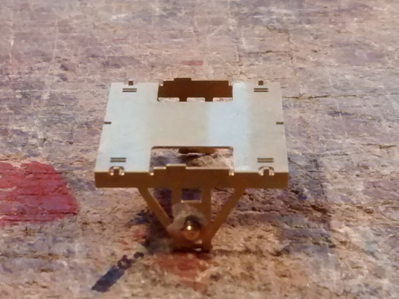
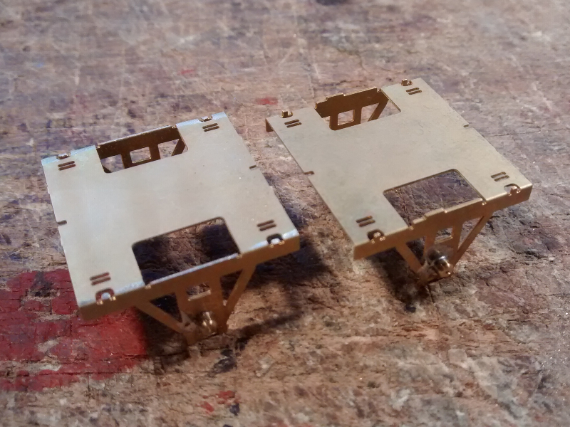
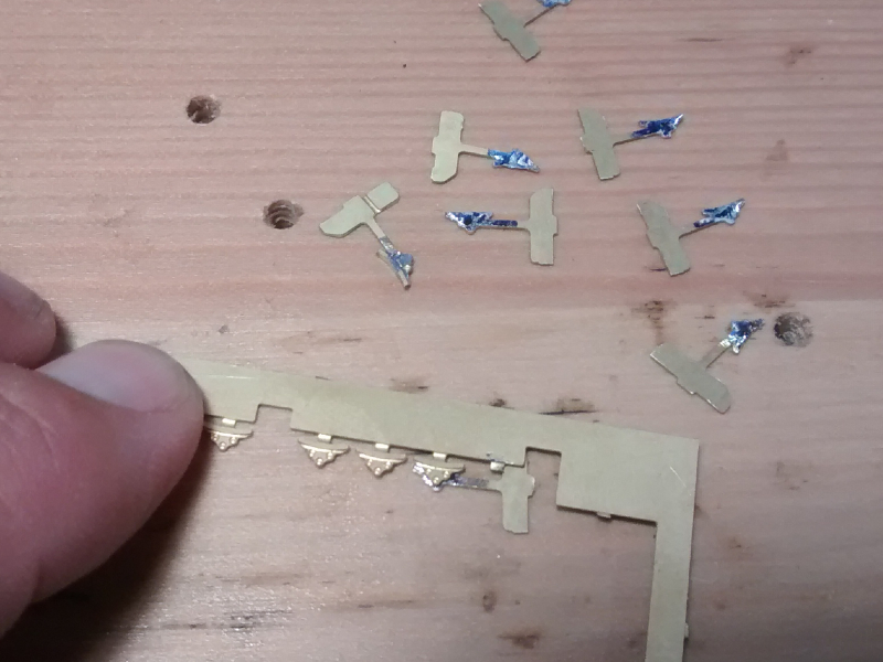
The two configurations of ‘W’ iron unit.
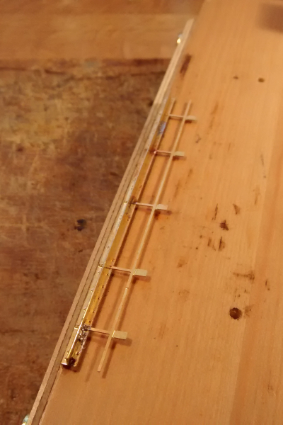
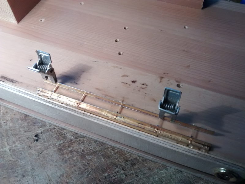
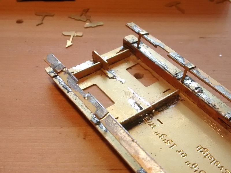
At the far end of this chassis there are two alternative sets of slots to locate the guides for the rocking ‘W’ iron.
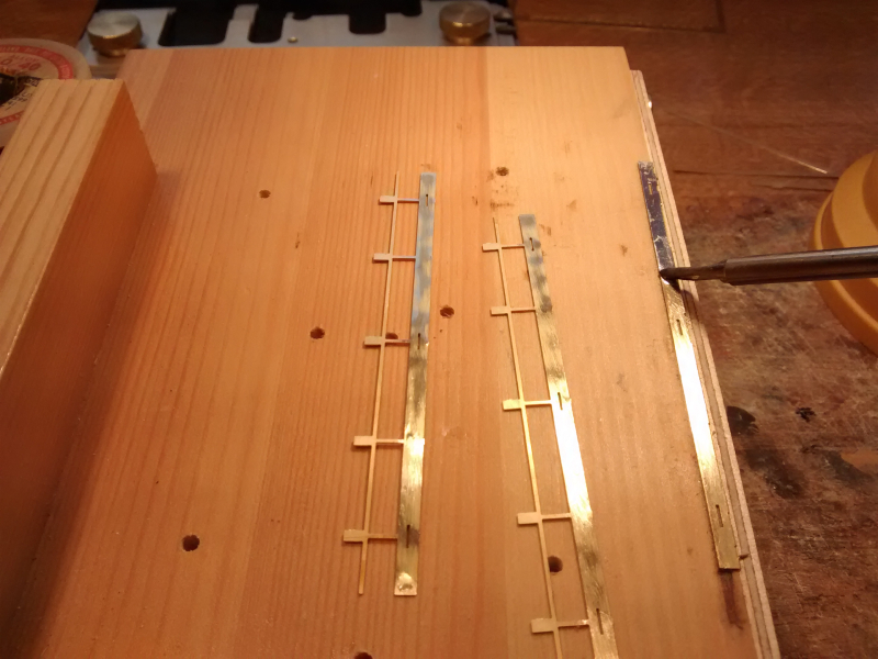
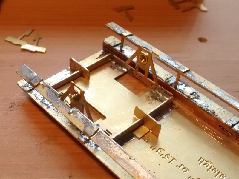
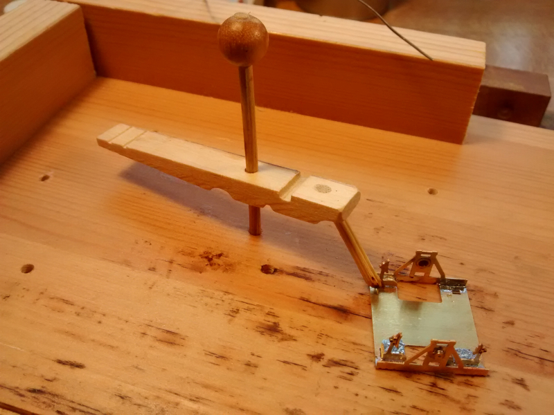
Both guides and one ‘elephant’ in place. The bottoms of the ‘tee’ shaped guides form the centre bearing surface for the ‘W’iron.
The ‘W’iron slotted into position and now the other ‘elephant’ can be fixed in place.
Brakes
Tin the shoe area of the brakes and then they can be placed under the shoe overlays whilst these are still attached to the etch border for ease of holding. Cut through the tab and clean up both layers with a half round file before fitting.
You can fit the brakes either before or after the ‘W’irons are secured. They locate in one of two sets of parallel slots. Use the inner ones if building the chassis to 00 standards; use the outers if EM or P4. That way the brakes line up with the wheels.
That completes the etch assembly for the chassis. It would be possible to adjust it to
different wheel-bases and lengths. It
should also be fairly easy to remove the projections on both ‘W’ iron units and
arrange them to be sprung, rather than compensated, which some people
prefer. You would have to provide
guides at both ends of the chassis and arrange a way to mount spring wires.