Etched kit for Small England Engines of the Ffestiniog Rly in 4mm scale.
In 2019 I decided I wanted to model two or three of the Small England engines of the Ffestiniog Railway. I designed test etches which were fitted in spare areas at the bottoms of some of my sheets of coach etches. I built one of the models and it showed a couple of areas which could be improved. I was fortunate to be allowed to photograph the test model on Paul Holmes exquisite ‘Borth-y-Gest’ layout, for which I am grateful to Paul.
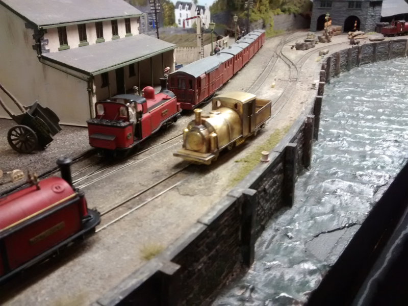
Hoping that there would be a market for the kits, I proceeded to revise the drawing, arranging it as organised etch panels for loco body, loco chassis and full tender. I decided to have it produced in 0.3mm thick nickel silver, like my 2mm scale kits, as I realised this would make it easier to solder. At this point, a major manufacturer announced that it was going to bring out a ready to run version. I imagined that would make the project non-viable, however several people asked me if I was going to continue, as the model I was making was to represent the prototypes around 1900. (It is based on the drawings prepared for the large scale Slater’s model which were published in Narrow Gauge and Industrial Review.
Cost of etches £70 + p/p
Some photos of the construction of the test etch:
I have learnt from building 2mm scale models that it is good to construct locomotive bodies on a strong flat base. The model ends up square, and it is easy to turn it around to get to different parts, and even hold it on edge in a vice as you work on it.
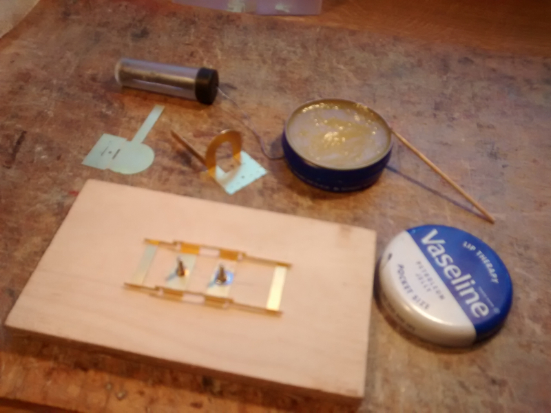
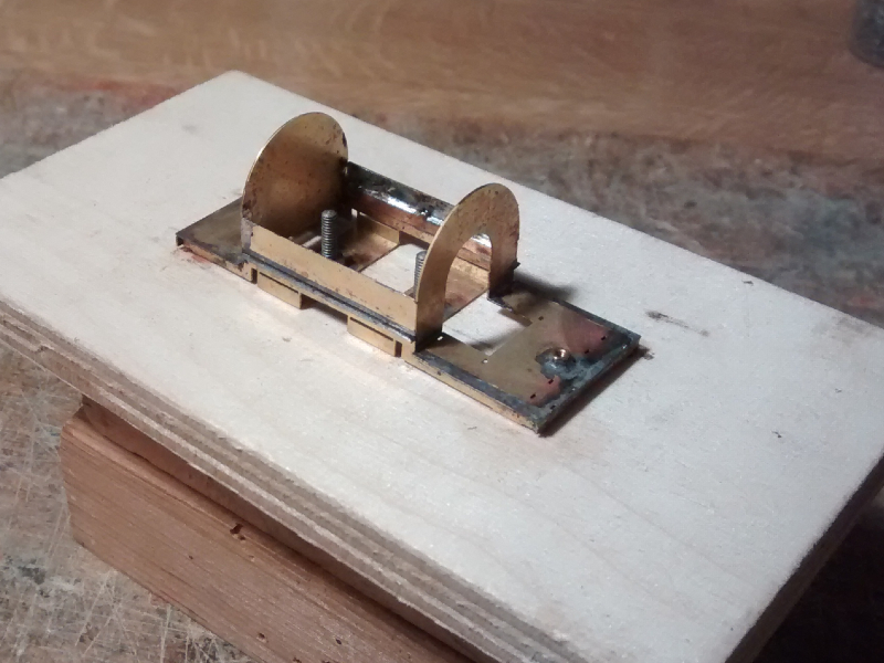
First stage in the assembly: Erection of the valances. The Vaseline stops the bolt from sticking when you solder the captive nuts onto the sacrificial spacers.
The footplates, front and rear of the tank and vertical sides of the tank carcass can be see in the background, being formed of two fold up assemblies which locate positively on the valances and with each other. One of them is folded to shape and ready for fixing.
Strong cages are added to form the tank, smokebox, firebox and cab to which detailed overlays are added. The nut you see on the footplate in the foreground (and another out of view in the smokebox area at the other end) line up with holes in the chassis etch.
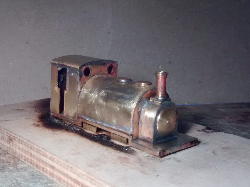
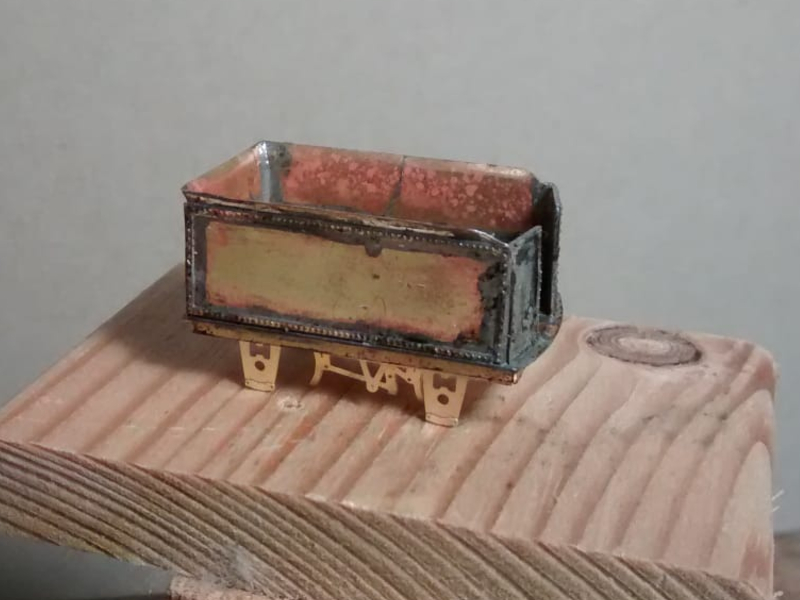
The body is still fixed to its rectangle of plywood. The small tabs joining the up-stands from the sacrificial spacers will be cut through and cleaned off, now the main assembly is complete. The captive nuts are already in the cab and the smokebox for fixing the chassis.
The tender chassis consists of two fold-up ‘L’ shapes, one for either side, which get held by a single screw and a washer inside an area like an inverted tea tray formed by the valances and the buffer-beams. On the production etches I have allowed a little clearance so these can be insulated from the body and the tender used for split frame current pick-up.
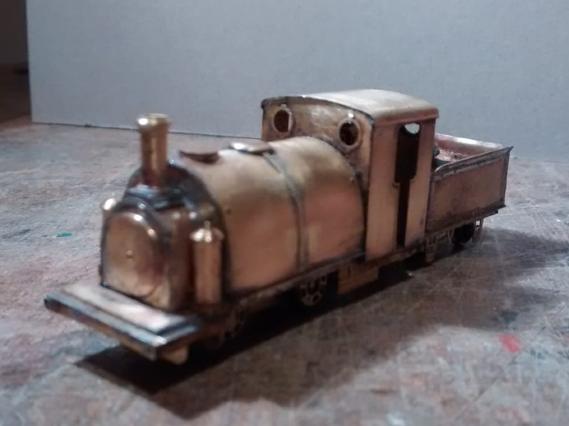
I will have more to say about the chassis construction when I provide the step by step illustrated construction sequence for the production models.
Contact me if you are interested.